← Back to Agentic Workflow Guide
Chapter 4 Control Flow
How execution moves through the graph
Chapter 3 defined the shape of the graph — which nodes exist and how they connect. Now we ask: when a node finishes, what happens next?
Topology is the map. Control flow is the journey along that map. The same topology can produce different behaviors depending on how control flow is configured.
4.1 — Types of Control Flow
Every transition in the graph uses one of four control flow patterns:
| Pattern | Description | Decided When? | Decided By? |
|---|---|---|---|
| Static | Always go to the same next node | Design time (when you draw the graph) | The edge itself |
| Conditional | Choose one of several next nodes based on a decision | Run time (based on input/output) | An LLM (Router Node) |
| Iterative | Repeat a subgraph until a condition is met | Run time (based on progress) | Iteration counter or LLM evaluator |
| Tool-driven | Continue calling tools or move forward | Run time (based on tool calls) | The LLM’s tool-calling behavior |
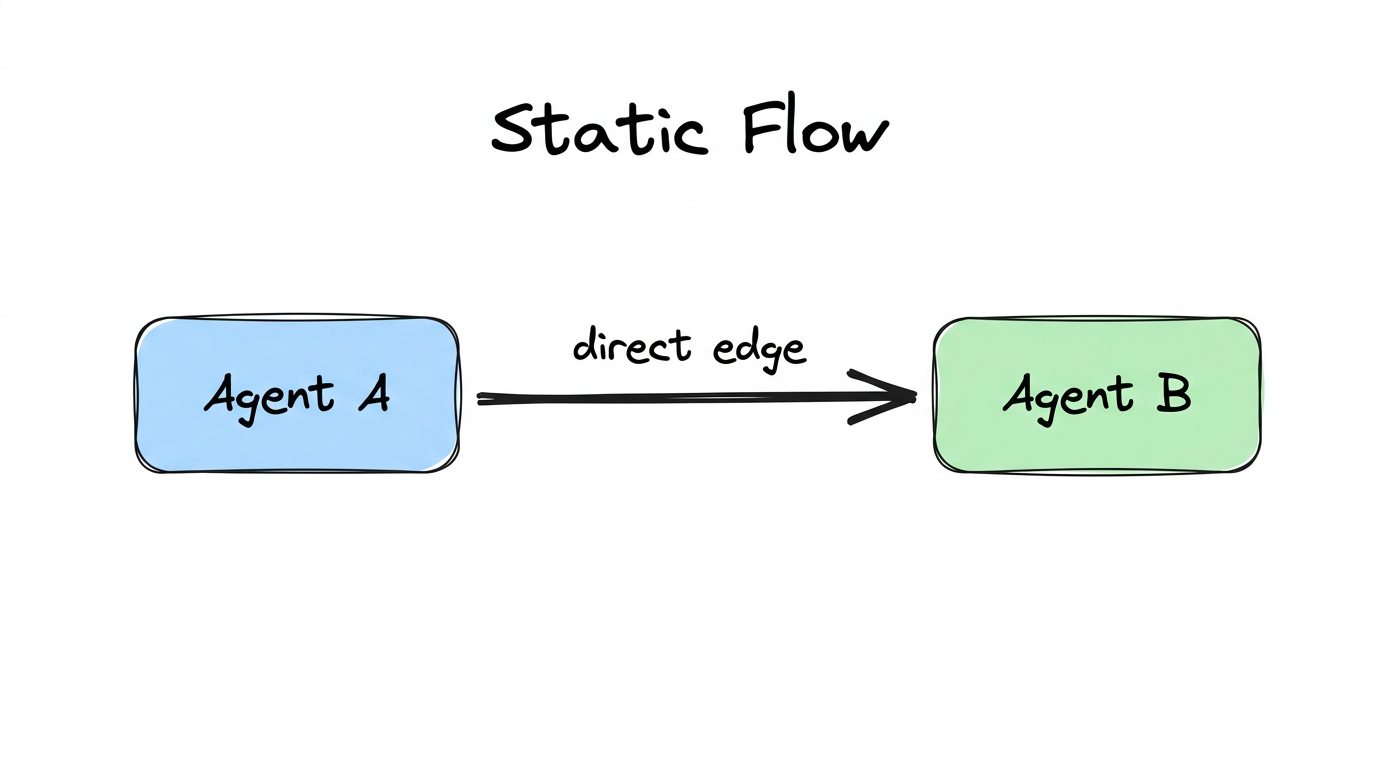
4.2 — Static Flow
The simplest control flow: when this node finishes, always go to that node. No conditions, no decisions. This is a direct edge in graph terminology.
# In code, this translates to a hard-coded destination:
next_node = "agent_b"   # Always the same
Every pipeline is built from static flow. It’s predictable, easy to debug, and easy to reason about. Use it whenever the next step doesn’t depend on the current node’s output.
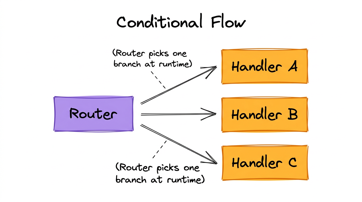
4.3 — Conditional Flow
The node looks at the current state and picks one of several possible next nodes. This is how Routers work.
# The Router LLM returns structured output:
{
  "next_node": "intrusion_handler",
  "reason": "The alert involves unauthorized access attempts,
            which matches the Intrusion Handler's expertise"
}

# The system routes execution to the chosen handler.
How the Router Makes Decisions
Under the hood, a Router Node uses structured output (a Pydantic model
called RouterDecision) to constrain the LLM’s response:
# The Pydantic schema that constrains the Router's output:
class RouterDecision(BaseModel):
    next_node: str   # Must be one of the available targets
    reason: str      # Why this target was chosen (stored for debugging)

# The Router Node's prompt includes the available targets:
"""Available routing targets:
- llm_4_node: "Malware Handler" (LLMNode)
- llm_5_node: "Intrusion Handler" (LLMNode)
- llm_6_node: "Misconfiguration Handler" (LLMNode)

Based on the conversation, which node should handle this next?"""
The structured output ensures the LLM returns valid JSON matching the
schema. The system then validates that the chosen next_node is
actually one of the connected targets. If the LLM hallucinates a target
that doesn’t exist, the system should fall back to a safe default
and log a warning.
4.4 — Tool-driven Flow
This is the most subtle and important control flow pattern. When an LLM Node has tools, it creates an implicit loop:
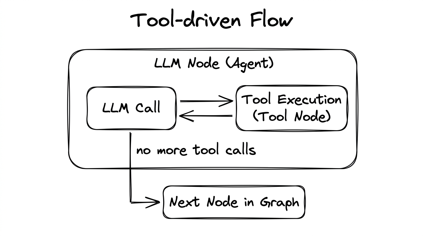
Here’s how it works step by step:
- The LLM is invoked with messages and a list of available tools.
- If the LLM’s response contains tool calls, execution goes to the Tool Node.
- The Tool Node executes the requested tools and returns results as
ToolMessageobjects. - Execution goes back to the LLM Node. The LLM sees the tool results in its message history.
- Steps 2–4 repeat until the LLM responds without tool calls (it has gathered enough information).
- Once the LLM gives a final text response, execution moves to the next node in the graph.
Tools + Structured Output: The Two-Phase Pattern
Many LLM frameworks have a limitation: structured output (JSON schema enforcement) disables tool calling. If you want an agent to both use tools and return structured output, you need a two-phase approach:
- Phase 1: Invoke the LLM with tools enabled (no structured output). Let it call tools and gather information.
- Phase 2: Once tool calling is done, re-invoke the LLM with structured output enabled (tools disabled) to produce the final formatted response.
4.5 — Iterative Flow
Iteration = control flow that includes a back-edge — a path that returns to a previously visited node. This creates cycles in the graph.
Bounded Iteration (Tool Loops)
The most common form of iteration is the tool-driven loop described above.
A hard limit (e.g., max_tool_iterations) prevents runaway loops:
# Tool Node enforces iteration limits:
def tool_2_node(global_state):
    current_iteration = global_state.get("node_2_tool_iteration_count", 0)

    if current_iteration >= max_tool_iterations:
        # FORCE the LLM to stop and give a final answer
        return Command(
            update={
                "messages": [HumanMessage(
                    content="You are out of tool calls. Return your final output now."
                )]
            },
            goto="llm_2_node"   # Go back to LLM for final response
        )

    # Normal: execute tool, increment counter, loop back
    result = execute_tool(tool_call)
    return Command(
        update={
            "node_2_tool_iteration_count": current_iteration + 1,
            "messages": [ToolMessage(content=result)]
        },
        goto="llm_2_node"   # Loop back for next LLM decision
    )
Open Iteration (Graph Cycles)
You can also create explicit cycles at the graph level — a Router Node that decides whether to loop back or move forward:
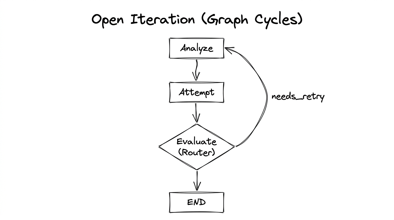
The Evaluate Router decides: “did we succeed?” If yes, route to END. If no, route back to Analyze for another attempt. You should always pair this with a maximum iteration count to prevent infinite loops.
4.6 — Edge Types
When designing a workflow graph, there are two fundamental edge types:
| Edge Type | Control Flow | When to Use |
|---|---|---|
| Direct edge | Static — always follow this path | Pipelines, fan-out connections, any fixed-route transition |
| Conditional edge | Dynamic — a router or evaluator decides at run time | Router branching, loop-or-exit decisions |
Tool-driven loops (the ReAct pattern) don’t need explicit edges. They are handled internally by the agent — the framework manages the LLM → Tool → LLM cycle automatically.
Chapter Summary
- Static flow: “Always go here.” Implemented with direct edges.
- Conditional flow: “The LLM decides where to go.” Implemented with a router + conditional edges.
- Tool-driven flow: “Call tools until done, then move on.” Automatic internal loop.
- Iterative flow: “Try again if not done.” Graph-level back-edges with a termination condition.
- The two-phase execution pattern solves the structured-output-disables-tools problem.
- Always set tool iteration limits to prevent runaway tool loops.