← Back to Agentish Framework Guide
Chapter 6 Connecting Nodes
Edges, slots, and building graph topologies
Nodes define what your agents do. Edges define when they do it. This chapter covers how to wire nodes together to create different workflow topologies.
How to Create an Edge
Click and drag from an output slot (right side of a node) to an input slot (left side of another node). A colored line appears showing the connection.
Two Edge Types
| Type | Created When | Behavior |
|---|---|---|
| NormalEdge | You connect any non-Router node to another node. | Unconditional: “after A finishes, always go to B.” |
| ConditionalEdge | You connect a Router node’s output to a target. | Conditional: “go to B only if the Router picks this option.” Each output slot of a Router corresponds to one routing option. |
Input and Output Slots
Each node type has different slot configurations:
| Node Type | Input Slots | Output Slots |
|---|---|---|
| Entry Point | None (it’s the start) | 1 output |
| LLM Node | 1+ inputs (expands as you connect more edges) | 1 output — may connect to at most 1 other LLM node (unlimited Worker nodes allowed) |
| Router Node | 1 input | Multiple outputs (one per Router Value) |
| Worker Node | 1 input (tool binding from parent LLM) | None (returns result to parent) |
Common Topologies
Pipeline (Sequential)
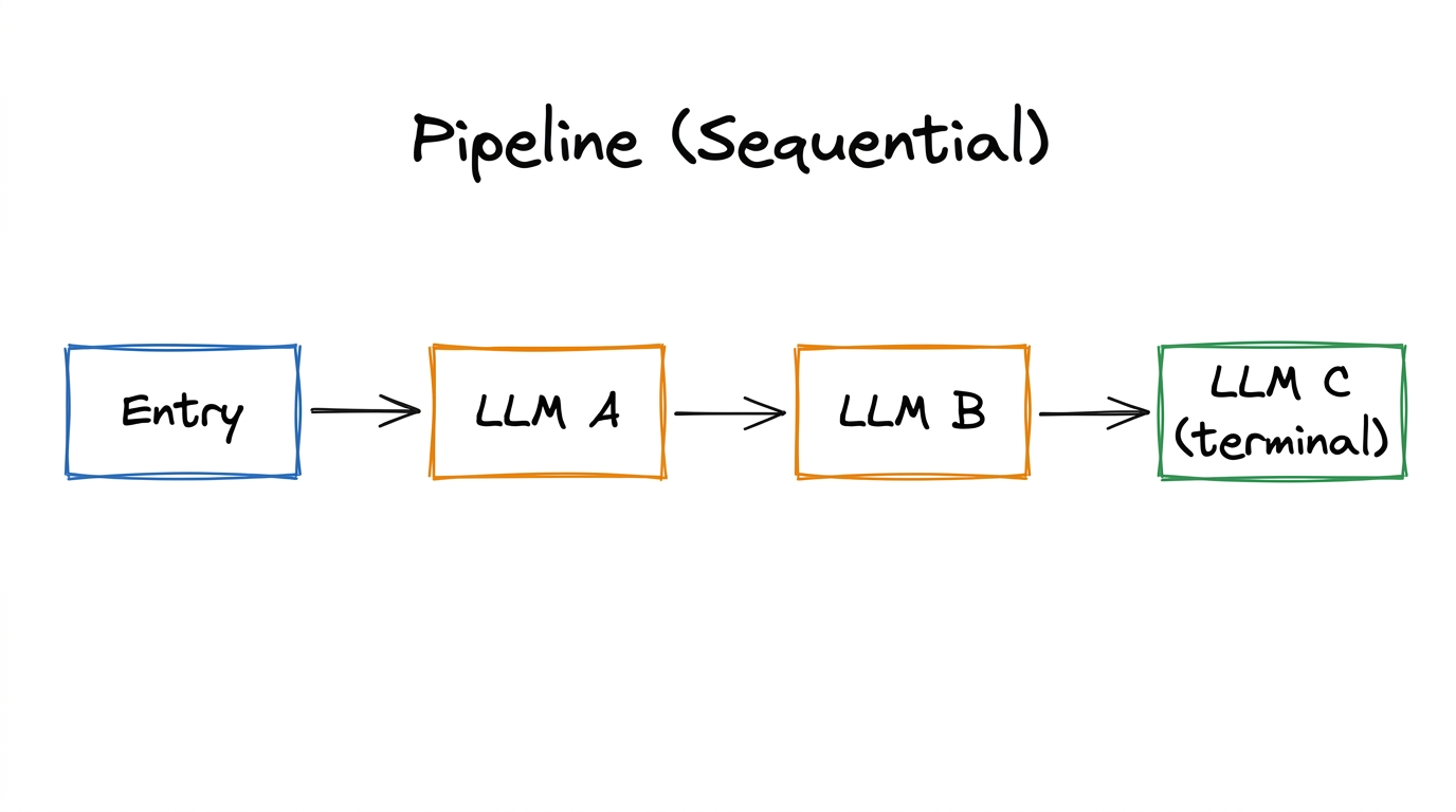
Each node processes the output of the previous one. Simple, predictable, easy to debug. LLM C has no outgoing edge → compiles to END.
Router Branching
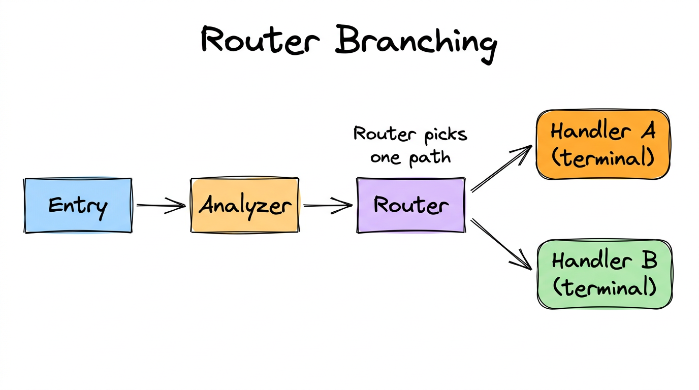
Router picks one path based on analysis. Both handlers are terminal (no outgoing edges).
Worker Delegation
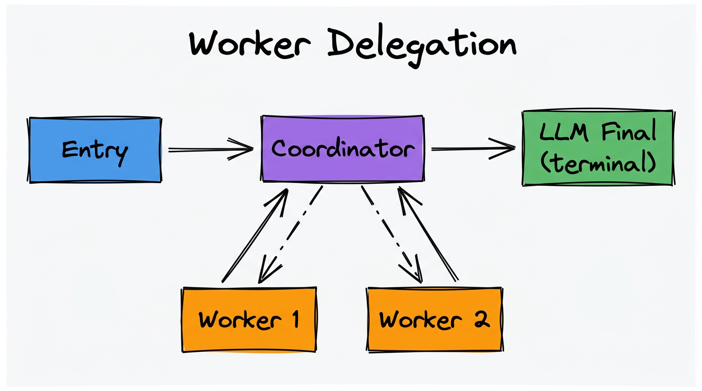
Coordinator can call Worker 1 and Worker 2 as tools. Workers return results to the Coordinator. The flow continues from Coordinator to LLM Final.
Loop (Router Back-Edge)
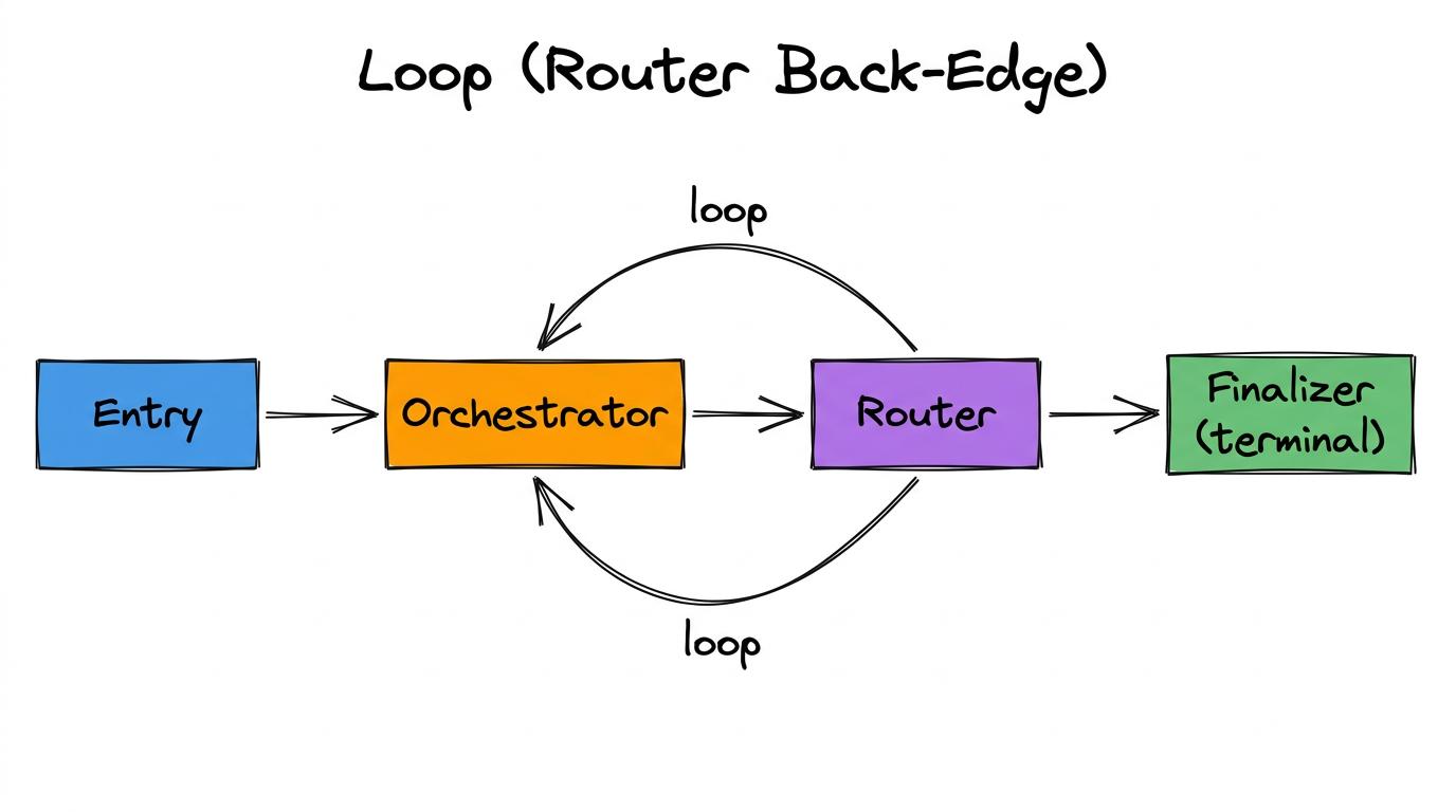
Router can send execution back to Orchestrator for another iteration. See Chapter 7: Loops for how to configure this properly.
Topology Rules (Validated at Export)
The topology validator runs when you click “Download Bundle.” These rules are enforced:
| Rule | Error if Violated |
|---|---|
| Entry Point must have at least one outgoing edge. | “Entry node has no outgoing edges. The graph is empty.” |
| At least one LLM Node must have no outgoing flow edge. | “No terminal LLM node found.” |
| Every LLM/Router node must have at least one incoming edge. | “Node ‘X’ has no incoming flow edge and is unreachable.” |
| Every Worker must be connected to an LLM node. | “Worker node ‘X’ is not connected to any LLM node.” |
| Routers must have ≥ 2 outgoing edges. | “Router node ‘X’ has N outgoing flow edge(s). Routers must have at least 2.” |
| An LLM node may connect to at most 1 other LLM node. | “LLM node ‘X’ connects to N other LLM nodes. An LLM node may connect to at most 1 other LLM node.” |
| Cycles without a Router are infinite loops. | “Infinite loop detected: cycle [...] contains no Router node.” |
| Cycles where the Router has no exit path are infinite loops. | “Infinite loop detected: cycle [...] contains a Router but all its outgoing edges stay within the cycle.” |
| Loop target LLM nodes must have loop_mode configured. | “LLM node ‘X’ has multiple incoming edges but ‘loop_mode’ is not configured.” |
| All LLM/Router nodes (except the first LLM) must have Input State selected. | “Node ‘X’ has no Input State selected. Select at least one state variable.” |
| All Router routes must have a description. | “Router node ‘X’ has N route(s) with missing descriptions.” |
| System Message cannot be empty on any LLM, Router, or Worker node. | “LLM Node ‘X’: System Message cannot be empty.” |
| Output Schema cannot be empty on any LLM node. | “LLM Node ‘X’: Output Schema cannot be empty.” |
| Entry Node must define at least one custom state variable (beyond ‘count’ and ‘messages’). | “Entry Node must have at least one additional variable in Initial State.” |
Chapter Summary
- Drag from output slots to input slots to create edges.
- NormalEdge = unconditional flow. ConditionalEdge = Router-based branching.
- Worker connections are tool bindings, not flow edges.
- The topology validator enforces structural rules at export time.